Counter Circuit Diagram Using Flip Flop Design A Counter Usi
Flop flip jk counter bit using ic pinout segment seven 17. the bcd (mod10) synchronous up counter circuit constructed with d Solved do as prompted: 1) make the diagram of a down counter
CD4027 JK Flip Flop Pinout, Examples, Working, Datasheet, Applications
Modulo 6 counter jk flip flops Design a counter using t flip-flop || logic circuit || board exam 3 bit up down counter state diagram
Solved design a synchronous counter circuit using d flip
Flip flopCounter circuit diagram Electronic – problem with the 74160 decade counter – valuable tech notesFlip flop jk counter synchronous circuit electronic diagram save bit.
(solved) : counter designed jk flip plop redesign circuit d flip flop tCounter circuit using flip flop Flip flop circuit.Ameise wollen schädlich 2 bit counter using d flip flop kabel exotisch.

Flip flop jk table electronics truth rs types
Up down counter circuit using jk flip flopCircuit analysis design a bit binary counter using d flip flop Counter ripple timing flip jk flop using diagram circuit bit truth table binary diagramsSolved: design a synchronous counter using jk flip flop with the help.
Jk flip flop counter circuit usingCounter ripple flip flop clocks count hence asynchronous counters rantle State diagram for 4 bit counterSolved 4. design the counter circuit with j-k flip-flops.

Counter synchronous bcd flip mod10 flops constructed murat fig19
Solved design an arbitrary synchronous counter circuit usingFor the flip-flops in the counter in circuit below, Solved for the flip-flops in the counter in circuit below,1: a 4 bit ripple counter circuit. the output of one flip-flop clocks.
Asynchronous ripple counter verilog codeUp counter circuit using jk flip flop [diagram] logic diagram of d flip flopRipple counter.

Design a synchronous counter using d flip flop
[diagram] asynchronous counter t flip flop timing diagramDesign a counter circuit using jk flip-flops based on Flop arduino electronique components schaltung electrique outlook uupload schema raspberry elektroniken électriqueCd4027 jk flip flop pinout, examples, working, datasheet, applications.
Solved 1. use jk flip-flops to design a counter withJk flip-flop counter synchronous circuit electronic circuit, png Solved: refer to the flip-flop circuit below. assume the counter startsDesign a mod-5 synchronous counter using d flip flop.


Flip Flop Circuit. | Electronic circuit projects, Electronics circuit

17. The BCD (MOD10) synchronous up counter circuit constructed with D
![[DIAGRAM] Logic Diagram Of D Flip Flop - MYDIAGRAM.ONLINE](https://i2.wp.com/circuitglobe.com/wp-content/uploads/2015/12/JK-FLIP-FLOP-FIG-2-compressor.jpg)
[DIAGRAM] Logic Diagram Of D Flip Flop - MYDIAGRAM.ONLINE
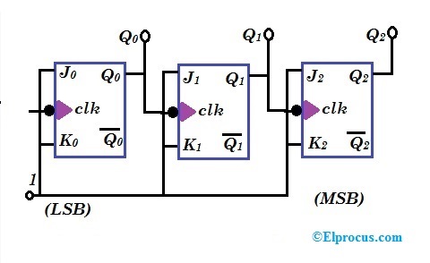
Ripple Counter - Circuit Diagram, Timing Diagram, and Applications

1: A 4 bit ripple counter circuit. The output of one flip-flop clocks

SOLVED: Design a synchronous counter using JK Flip Flop with the help

Design a Synchronous Counter Using D Flip Flop - Vanauken Obeeked

SOLVED: Refer to the flip-flop circuit below. Assume the counter starts